How to replace a broken mylar window on a Lytle Chamber
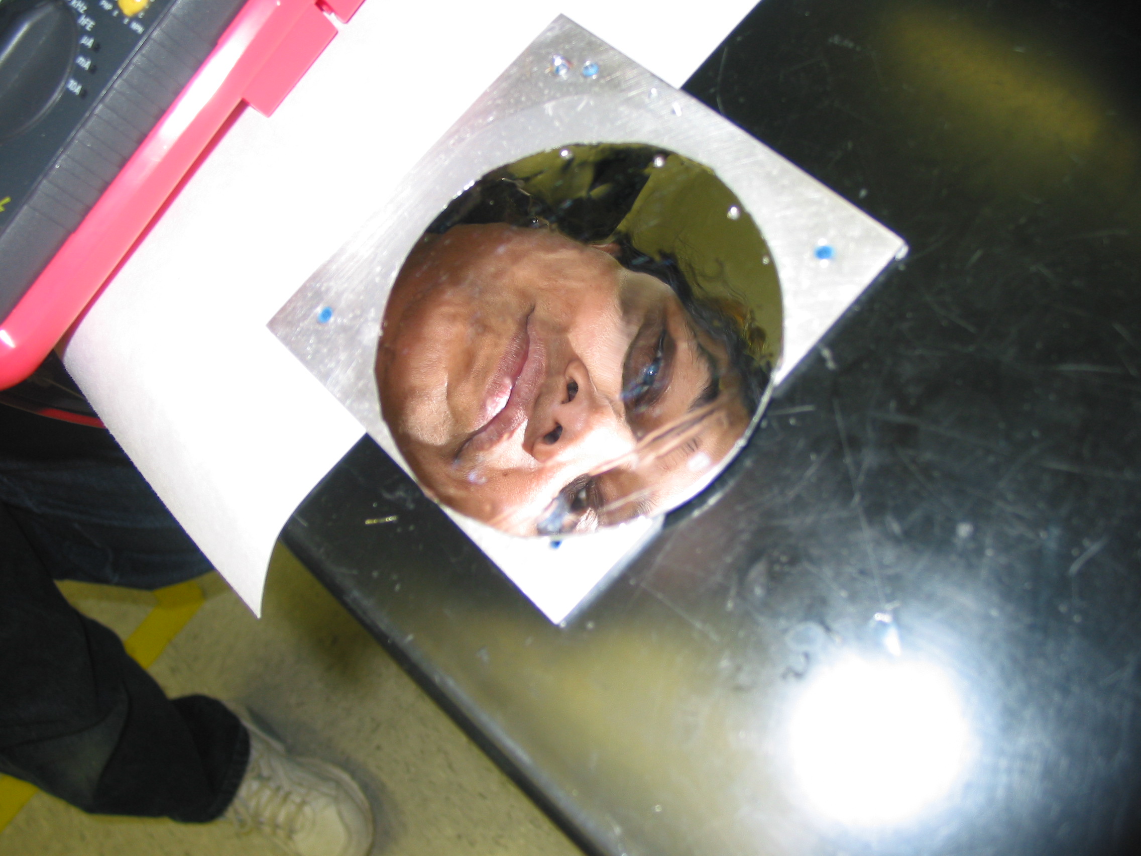
(Who is the original author of this piece? Presumably the person in Fig 6b… It would be nice to give credit…)
Step 1. Taking the plate apart from the detector
Note: This is definitely the most challenging step.
First, Take off all the mounting hardware and Soller slits. Remove the electronics as well (whether you need to put them back on is up to you – many of us don’t use these anyway, and send the signals straight to a commercial current amplifier like the SRS 570. Remove all the nuts, electric connectors and gas connectors.
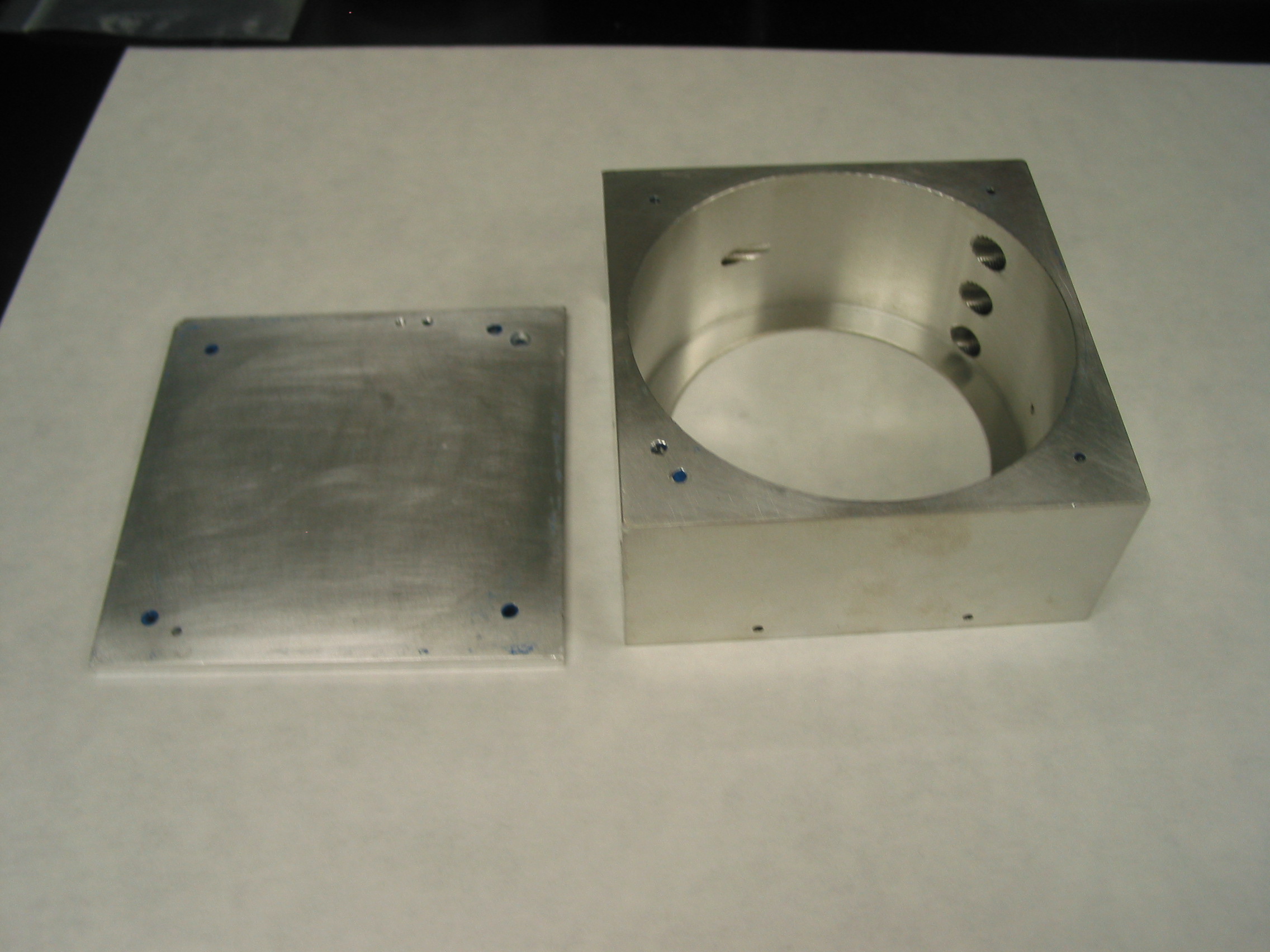
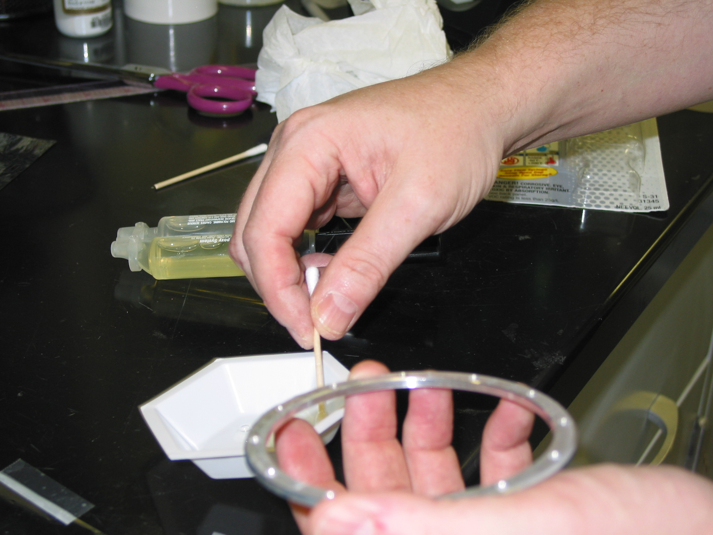
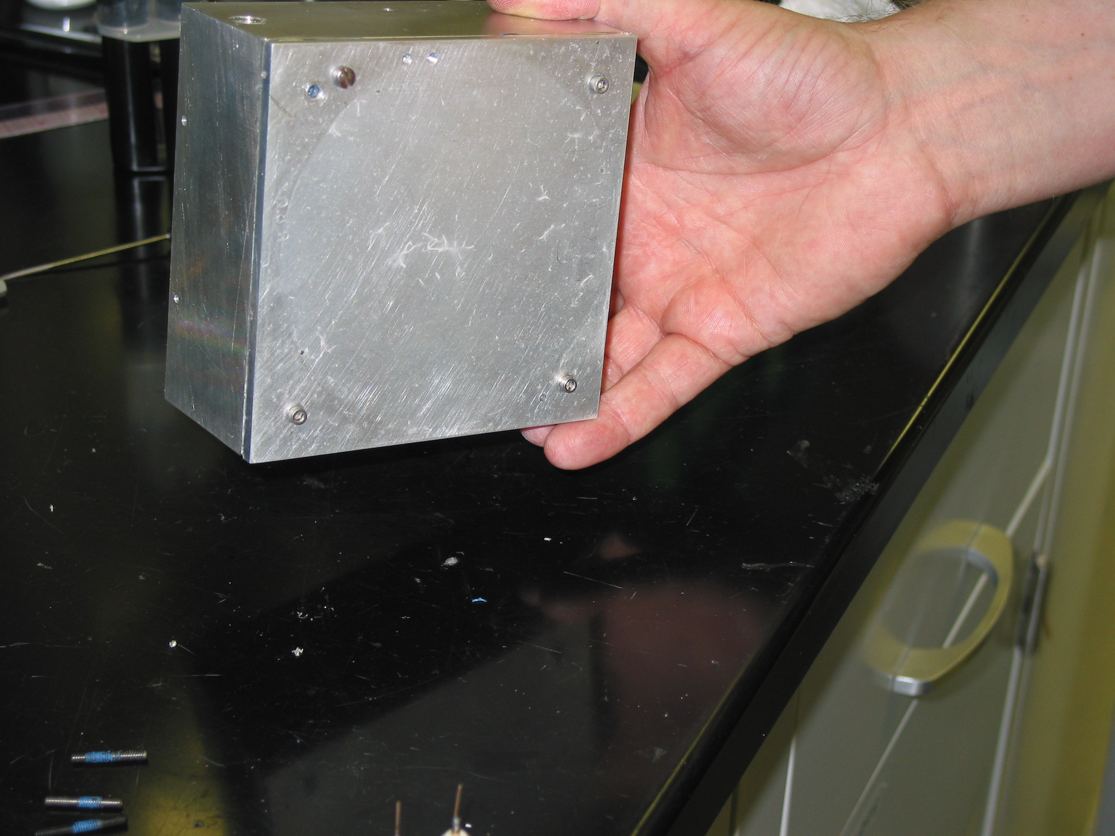
The back plate (where the electronics attach) is usually sealed to the chamber with a blue silicone material (RTV). Soak this in acetone for 24 hours, then pry it apart with a knife. The silicone is a real mess, and depending on the chamber, you might need to hammer it apart. We prefer to reassemble with Devcon 2 ton epoxy (Fig 1), which is strong, can make an air seal, and dissolves more easily in acetone.
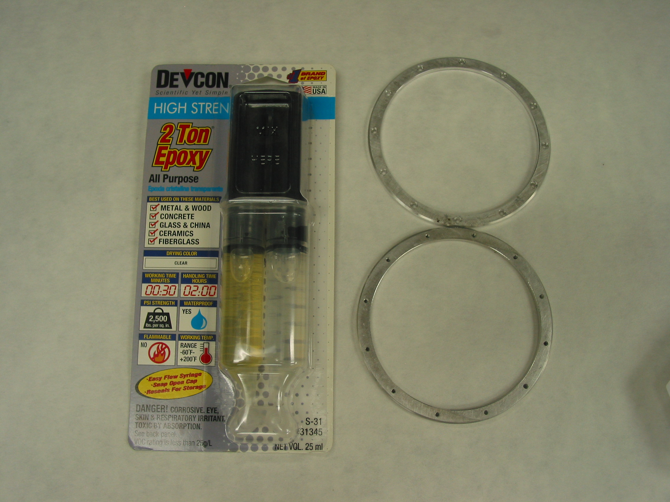
Fig 1. Devcon 2 ton epoxy. Don’t leave home without it.
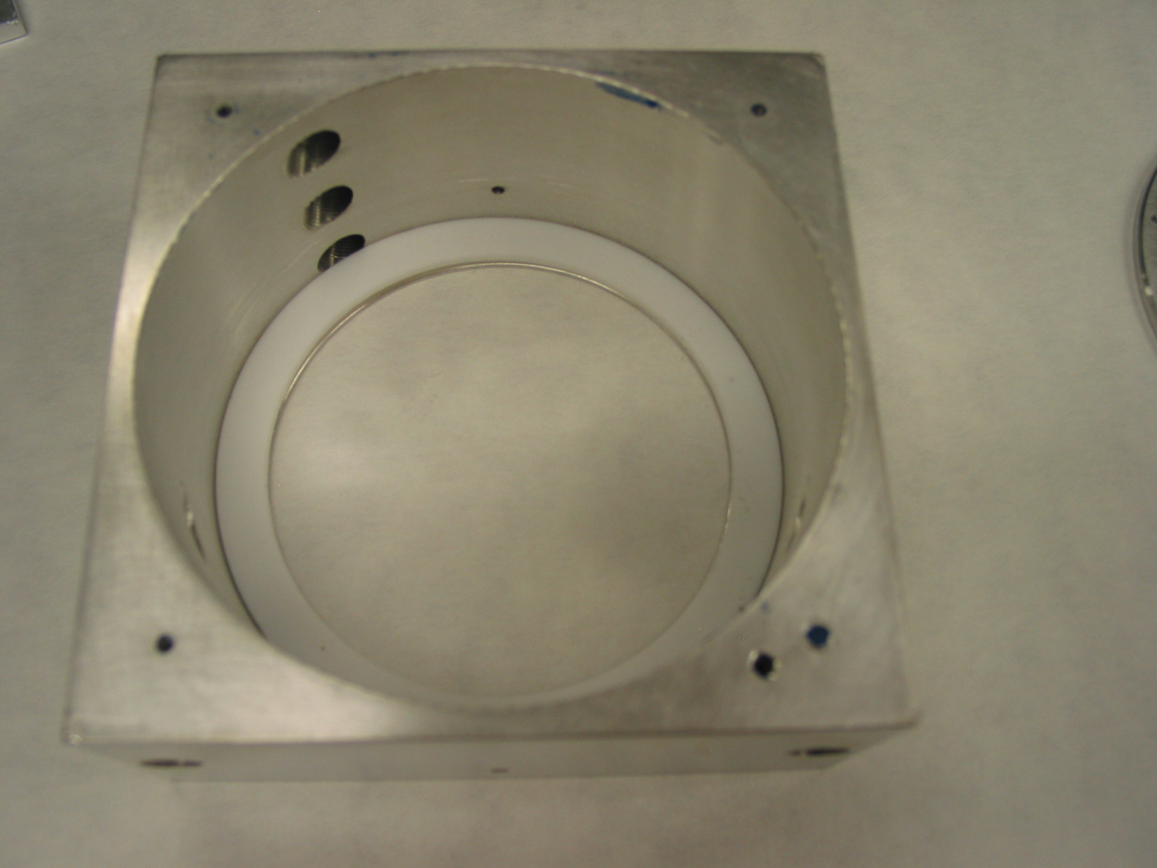
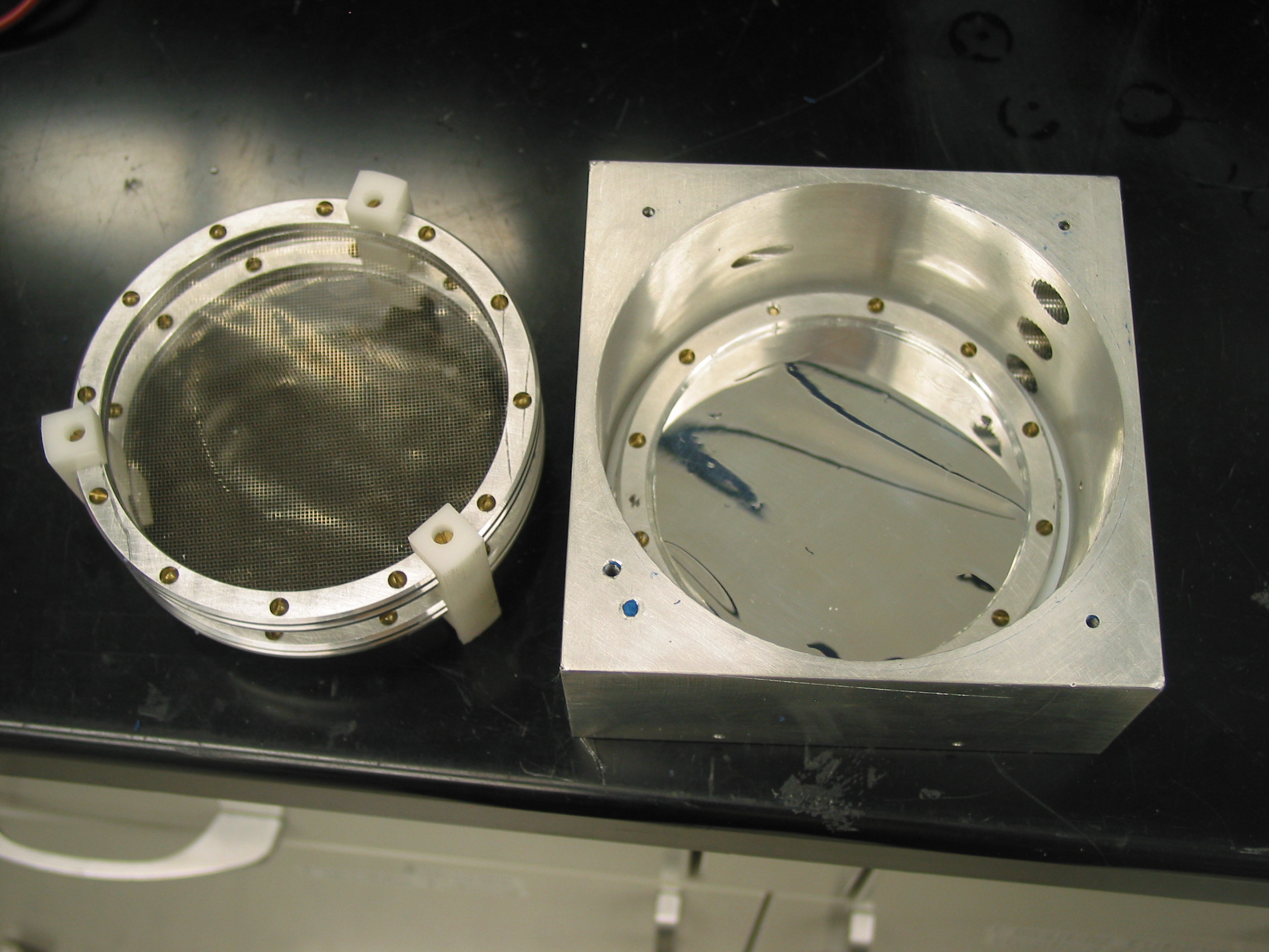
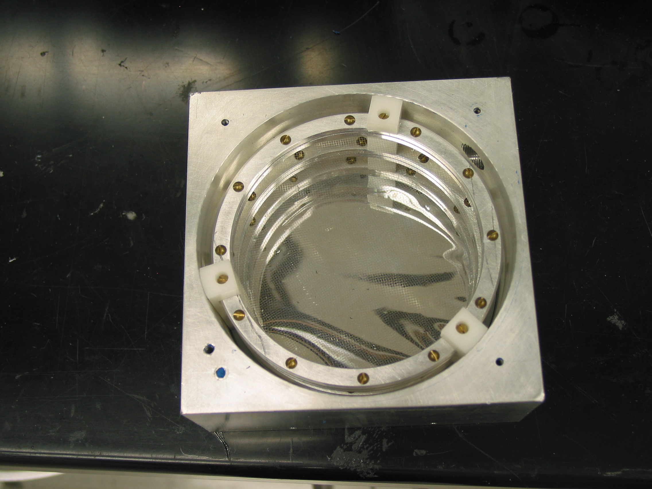
You’ll also need to get the front mylar window off. The mylar is attached to an aluminum ring and separated from the outside box by a teflon spacer. Again, use acetone to loosen the epoxy. Pull out the assembly of collecting plates (Fig 2). The one shown has two Ni mesh grids for the middle plate (high voltage) and the back collecting plate. In our experience, these Ni mesh windows are pretty fragile and easily broken, but can be replaced with aluminized mylar using the same procedure described in the next section.
Just to be clear, each of the three plates (one HV in the middle and two collecting plates in front and back) consists of two aluminum rings with a Ni mesh or aluminized mylar window between them. The rings are screwed together to hold the window. The screw heads always point toward the back of the detector. The rings are spaced apart by teflon holders that are slotted to hold the middle and back plate, and this whole assembly rests against the front plate.
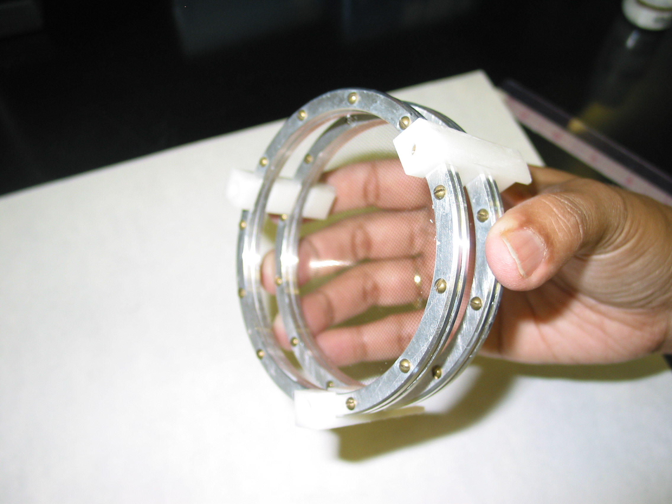
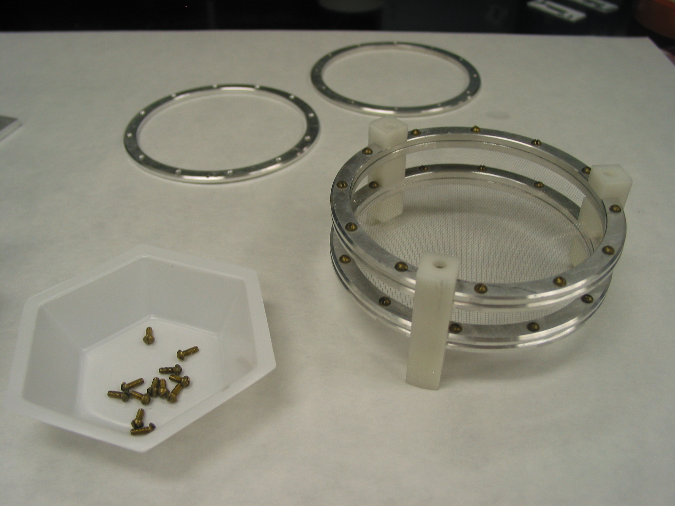
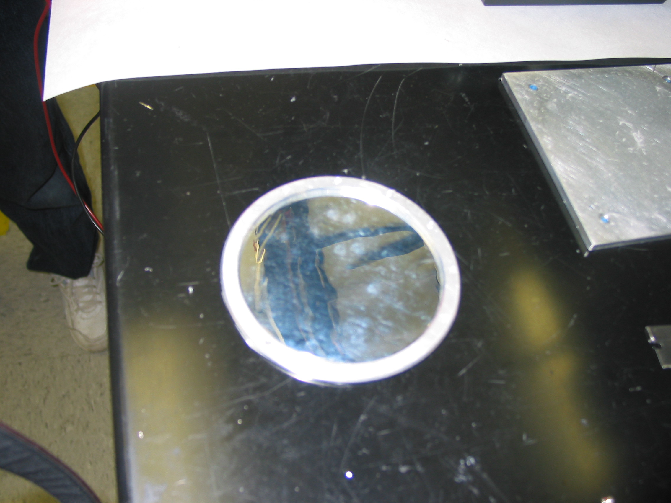
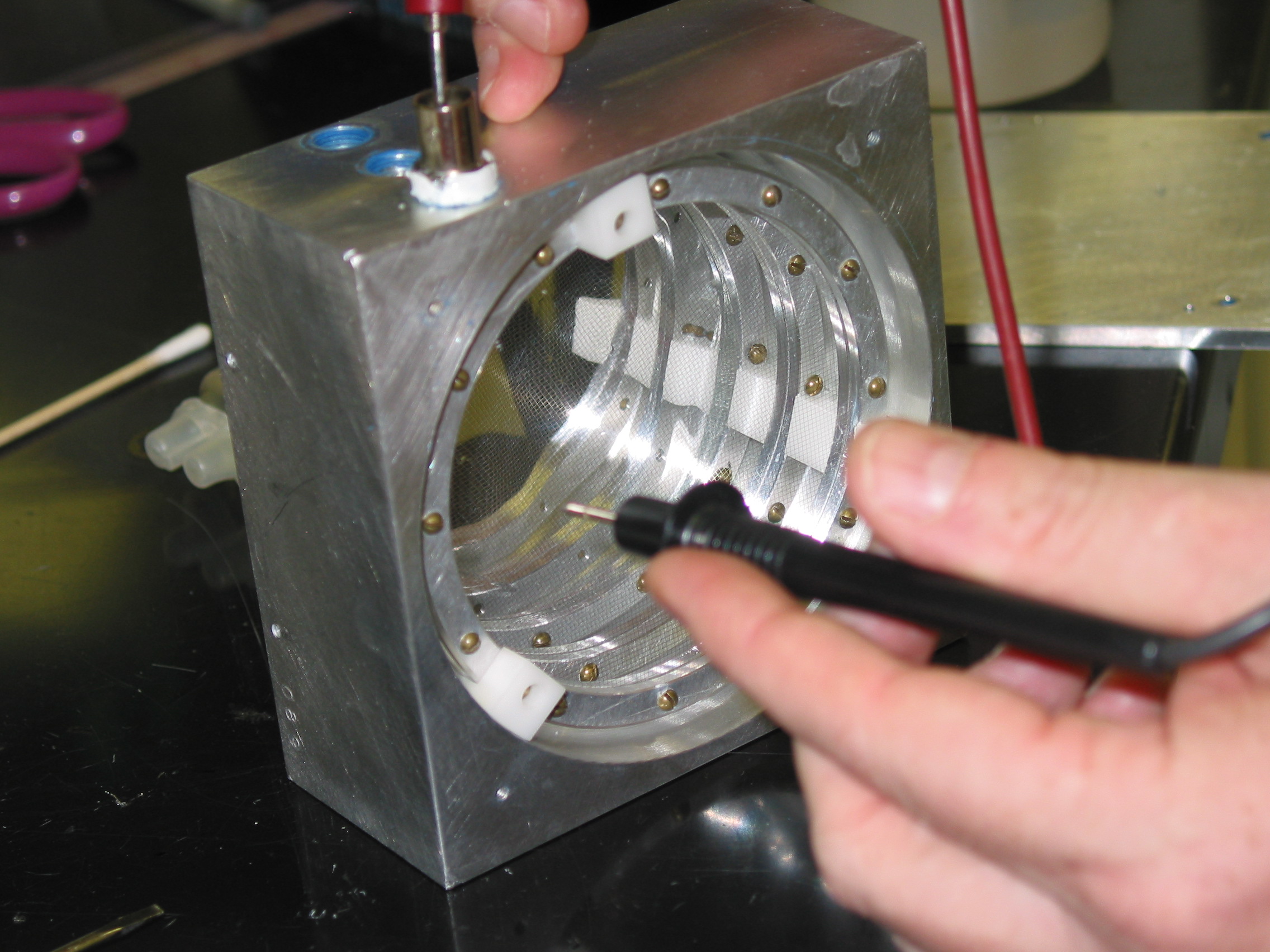
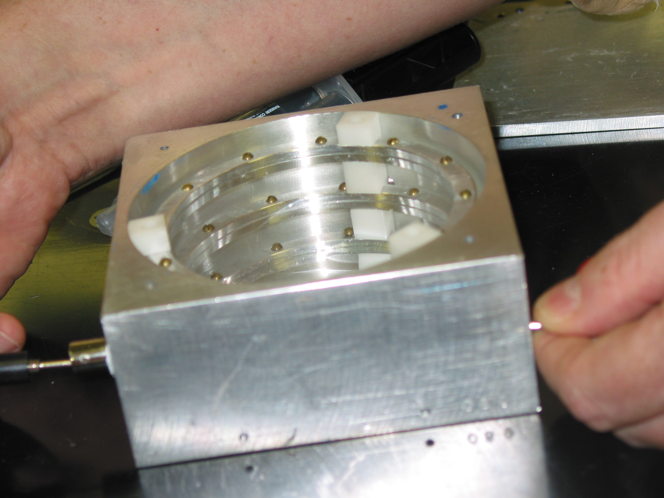
Fig 2. Collecting plates from Lytle Chamber with Ni mesh. The image on the right shows the middle (HV) and back plate still attached to the teflon spacers. In the back are the two rings for the front collecting plate (the front mylar window, having been punctured, was removed).
When your done, you’ll have a clean ion chamber and clean rings. See Fig 2 and Fig 3.
Step 2. Stretching the aluminized mylar
If you can get it, double-sided aluminized mylar is preferred, as both sides will conduct If you cannot get it, mylar coated on only one side is OK, but you may want to use silver print or conducting paint to make electrical contact. Make sure you know which side is conducting with a multi-meter.
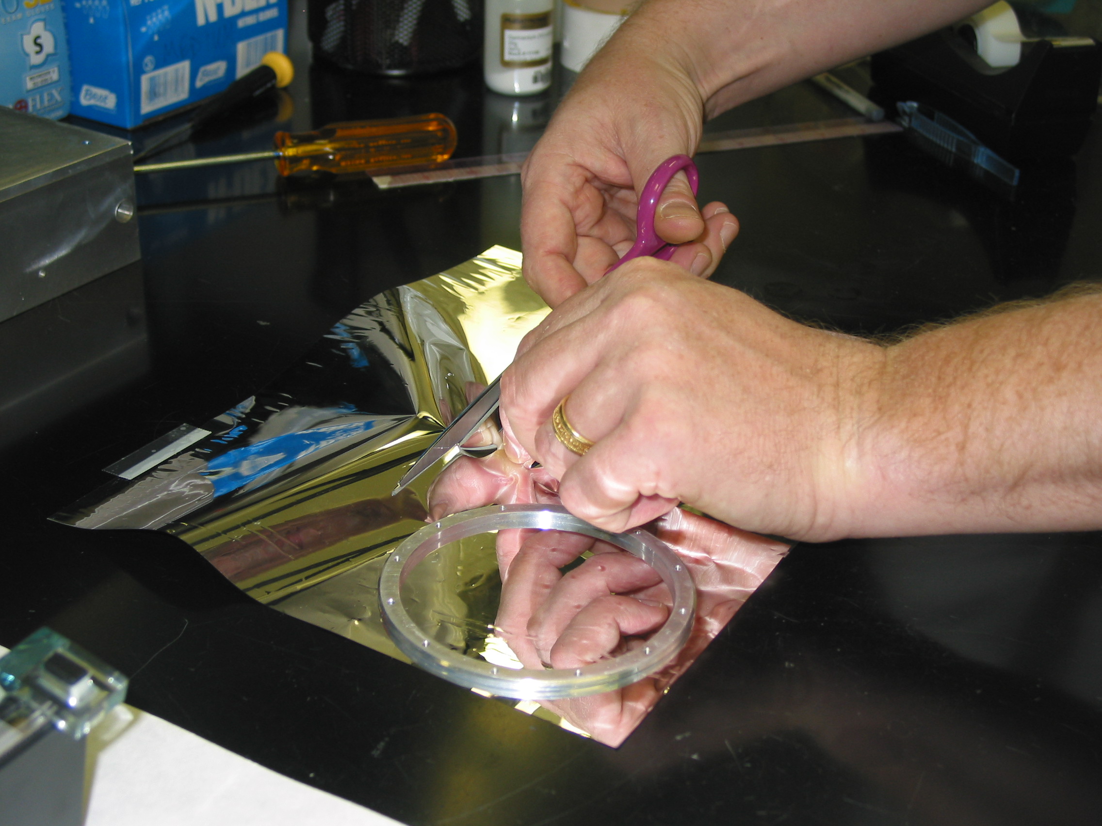
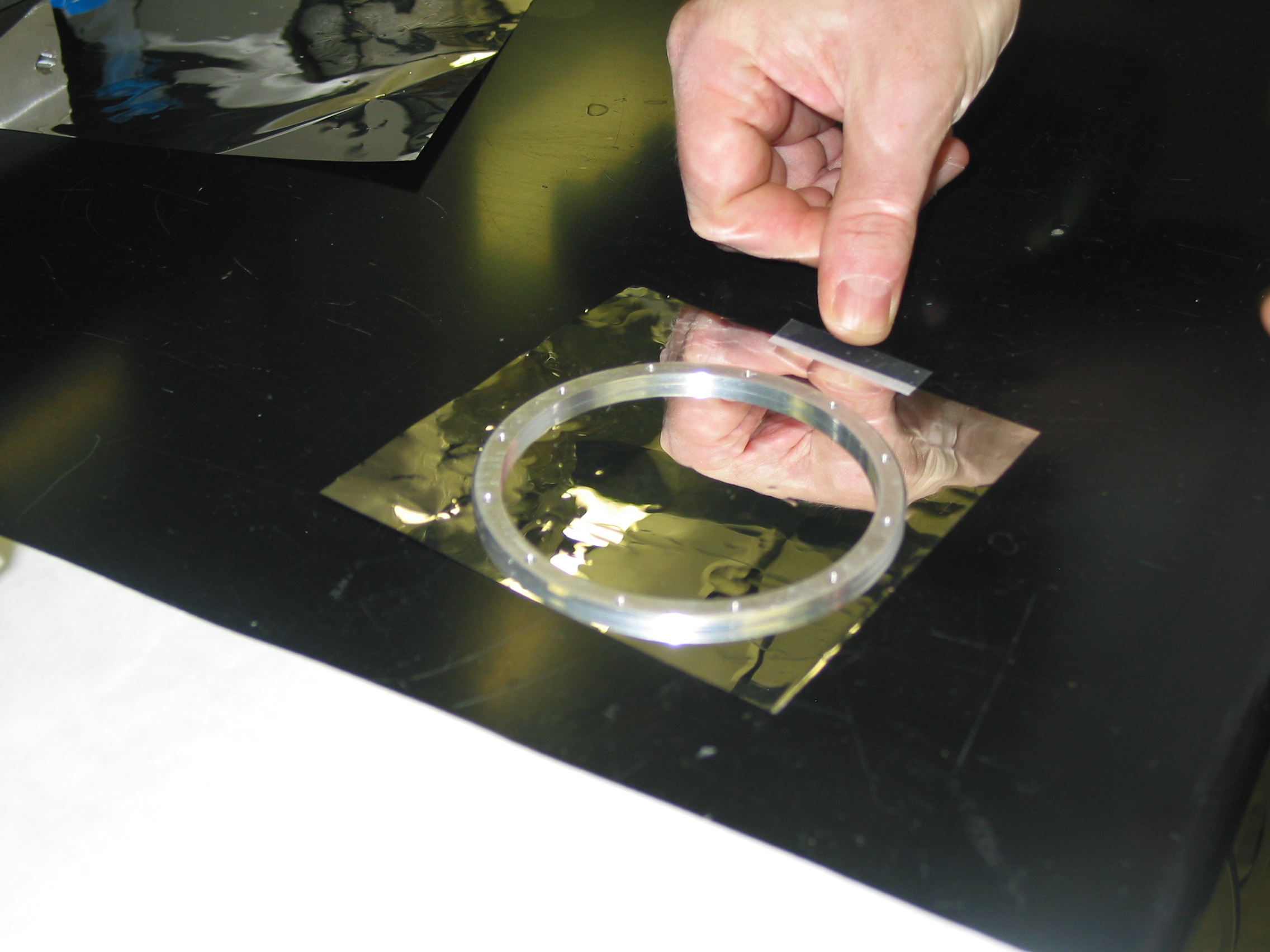
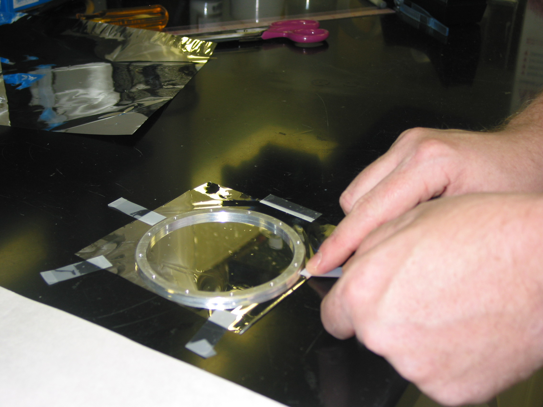
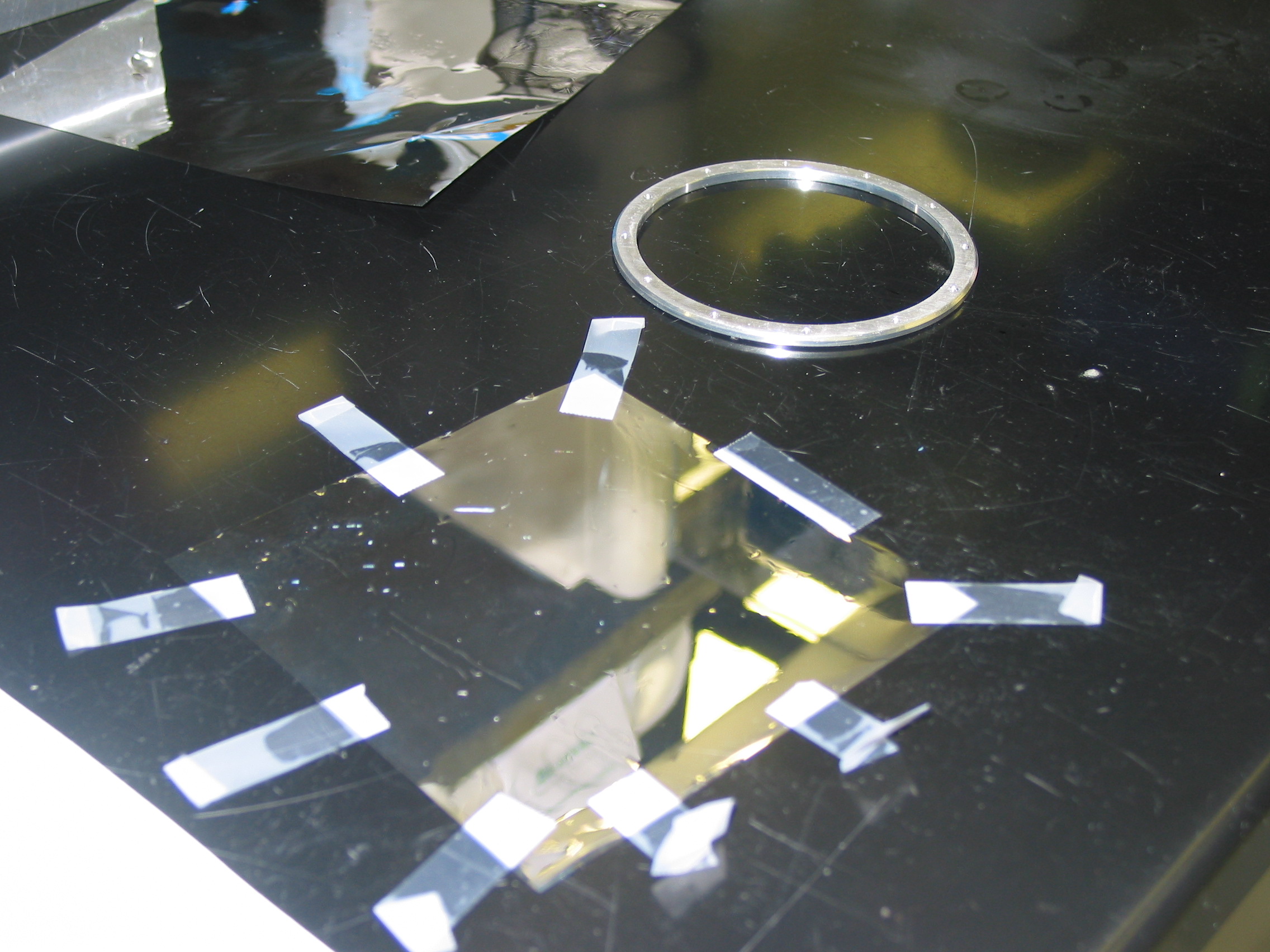
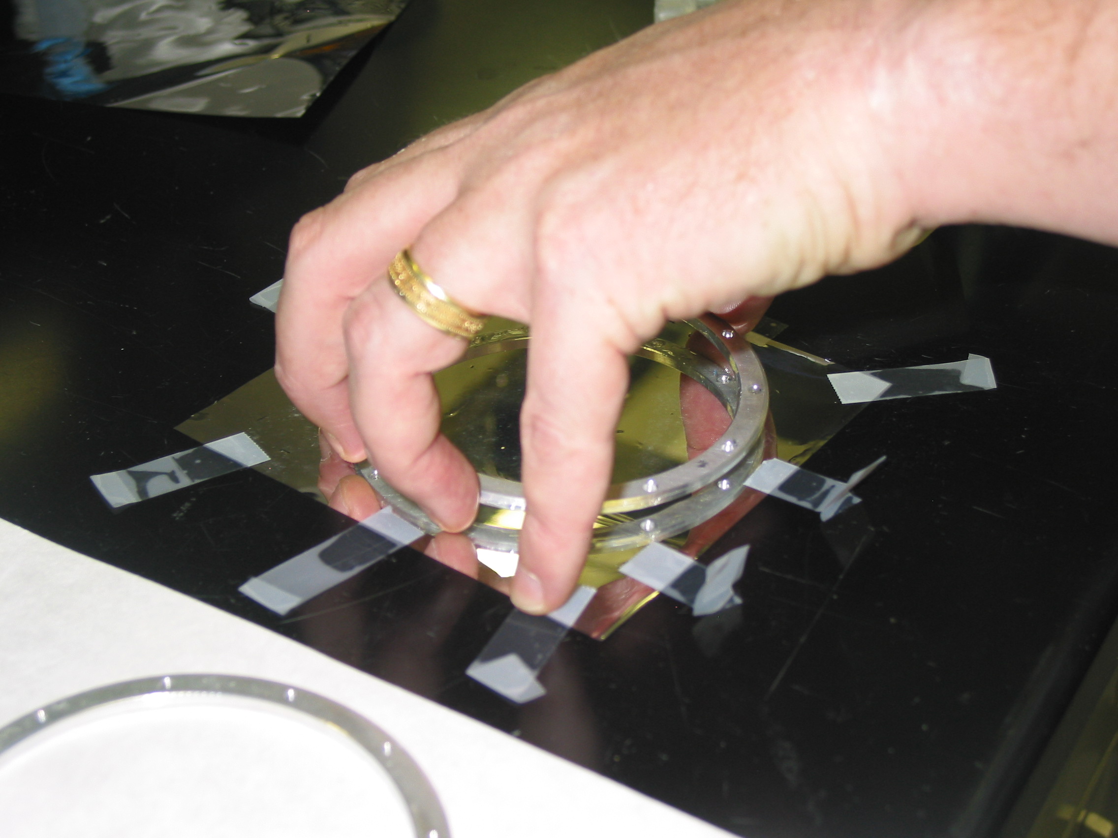
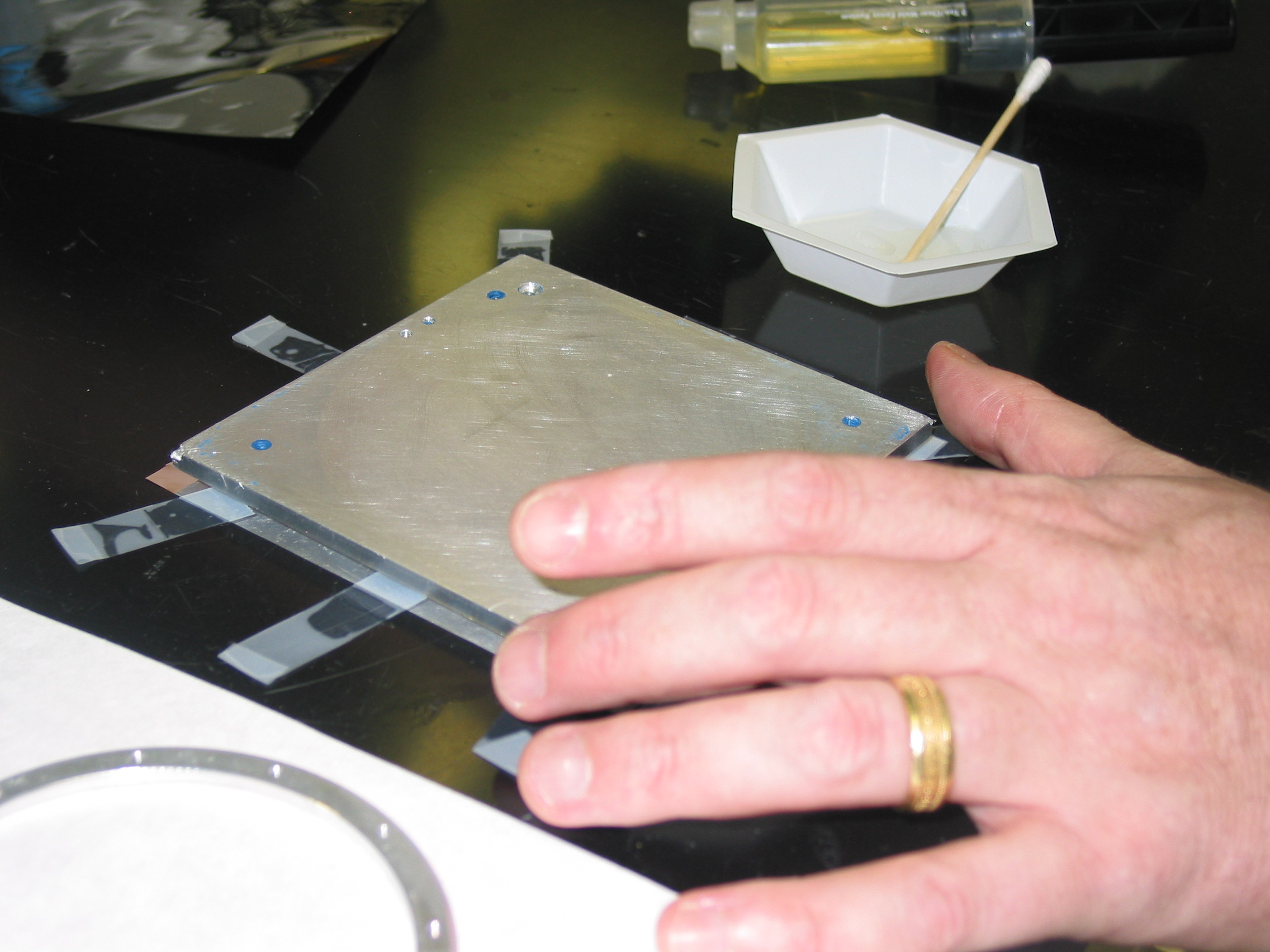
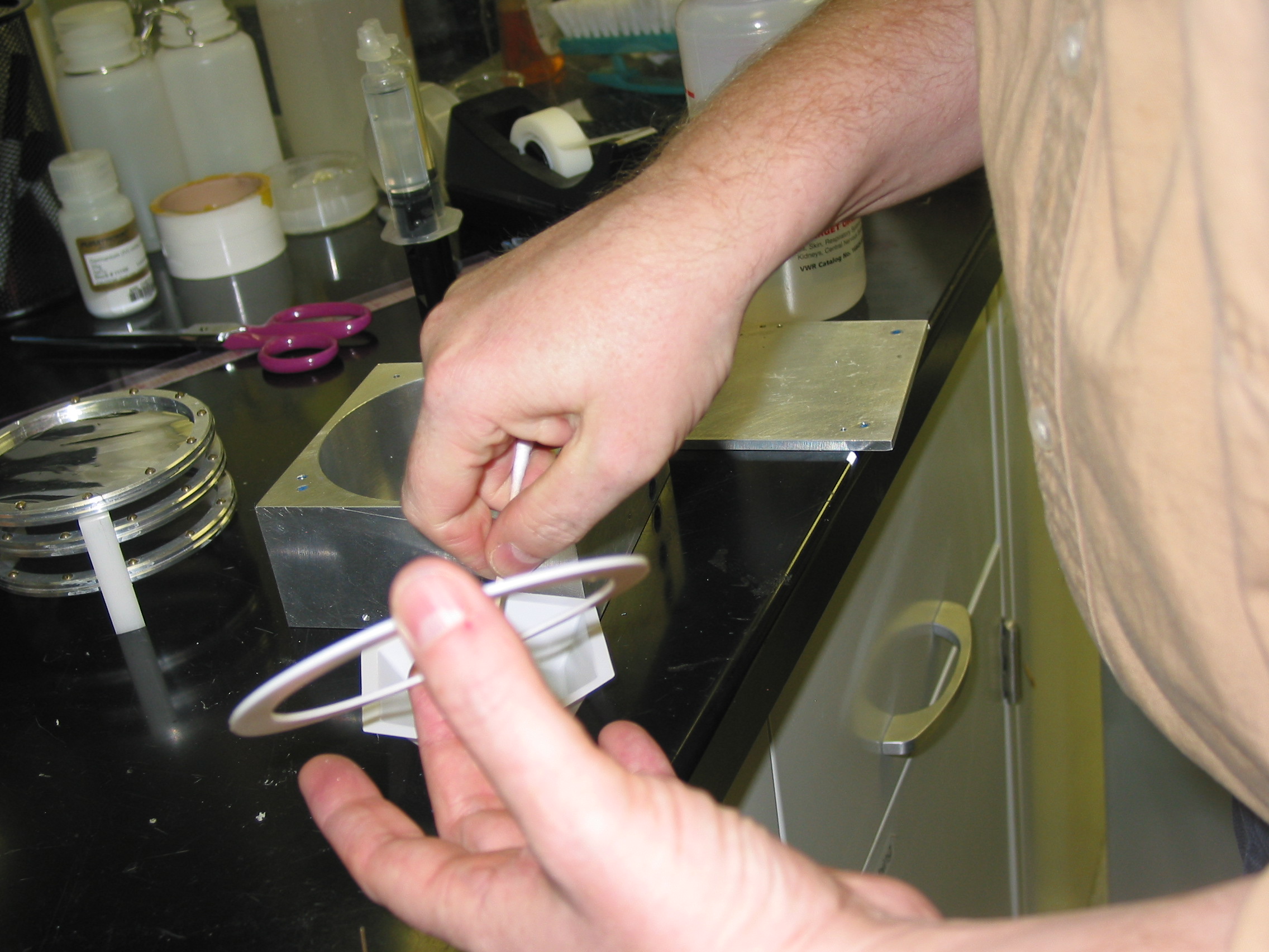
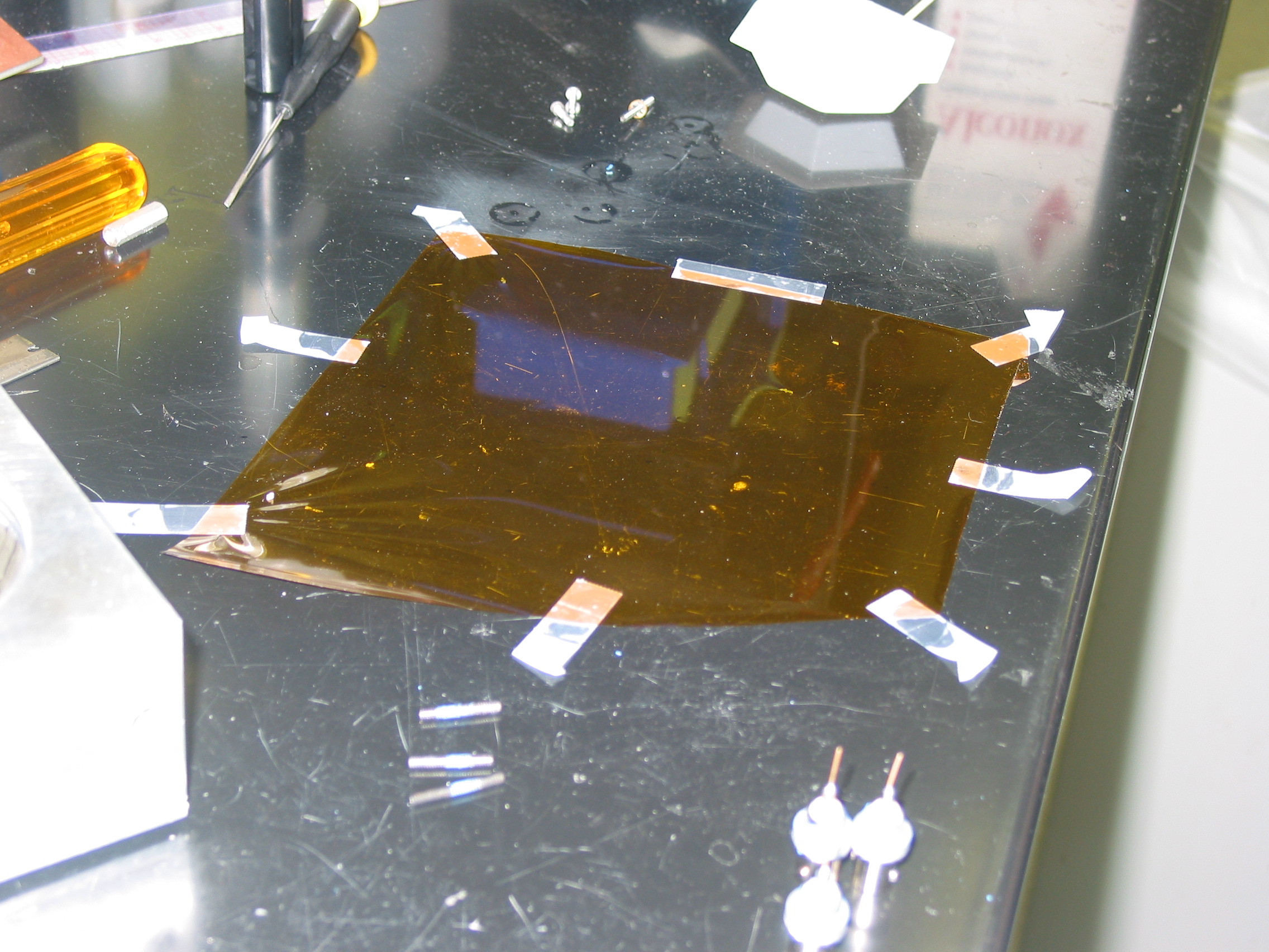
The goal here is to stretch out a piece of mylar and glue it to the aluminum ring. See Fig 4.
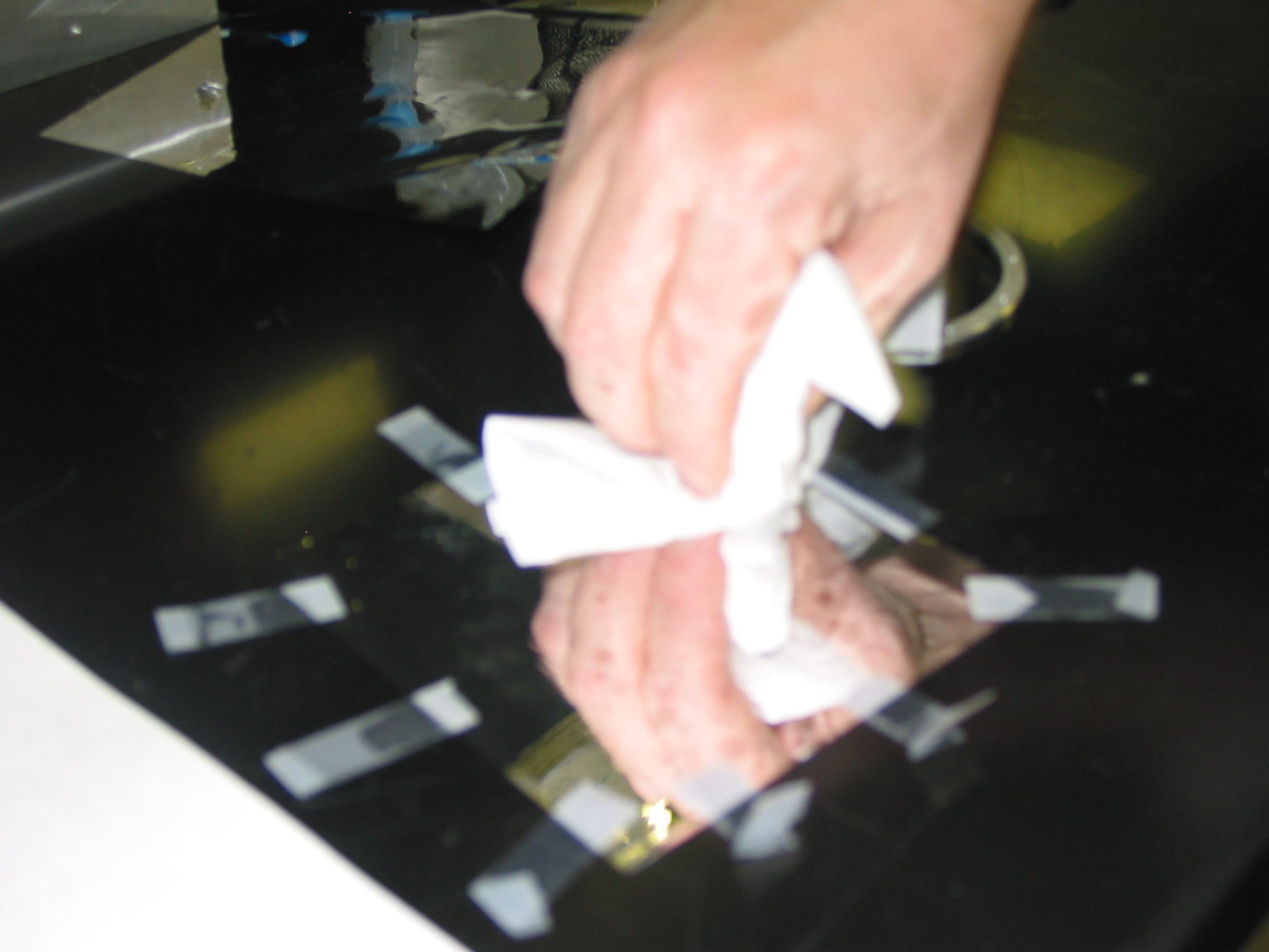
Clean the surface of the table. The surface should be smooth.
2. Cut a piece of the aluminized mylar bigger than the ring and put it on the table ‘’’with a conducting surface down’’’.
3. Use scotch tape on one corner of the mylar and stick it on the table. Then stretch it in a clockwise direction and put another piece of scotch tape. Go on stretching about 1-1.5 cm and put scotch tape on the stretched part. Do this till the whole mylar is stretched out pretty nicely and looks taut. This is a very important step since presence of wrinkles will give rise to noise.
Step 3. Epoxy the Ring to Mylar
Clean the mylar window, mix a small amount of epoxy and completely cover the threaded aluminum ring with a thin coat of epoxy. Place the ring on the mylar and put a block (say, the chamber itself) on top of the ring to press it down. It’s often helpful to add a piece of paper between the ring and the weight, so that the weight does not become epoxied to the ring. Wait a good solid 24 hours for the epoxy to dry. For the repair pictured here, we didn’t wait long enough, and the mylar window did not end up very tight.
Step 4. Screw the two halves of the front ring together
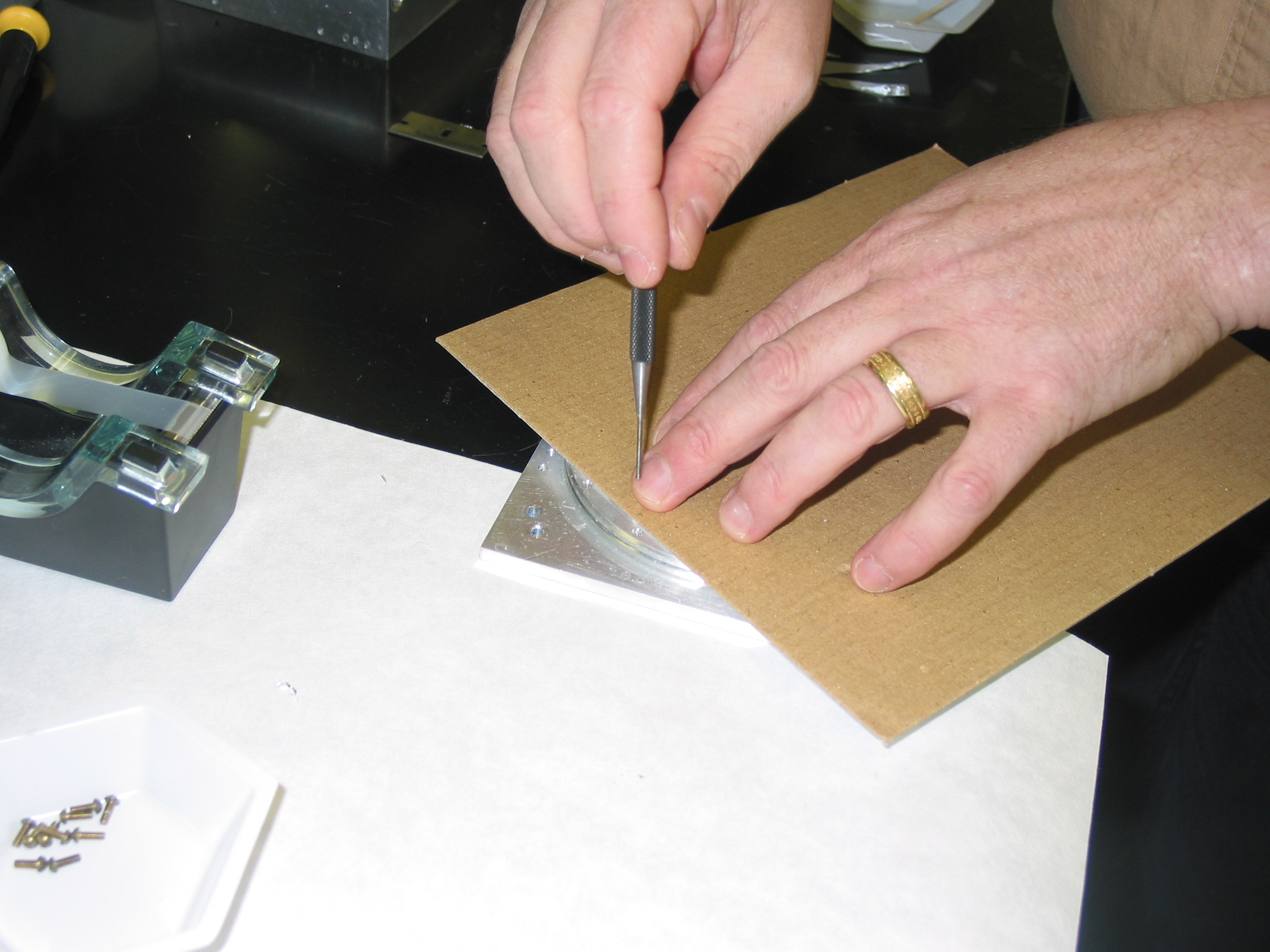
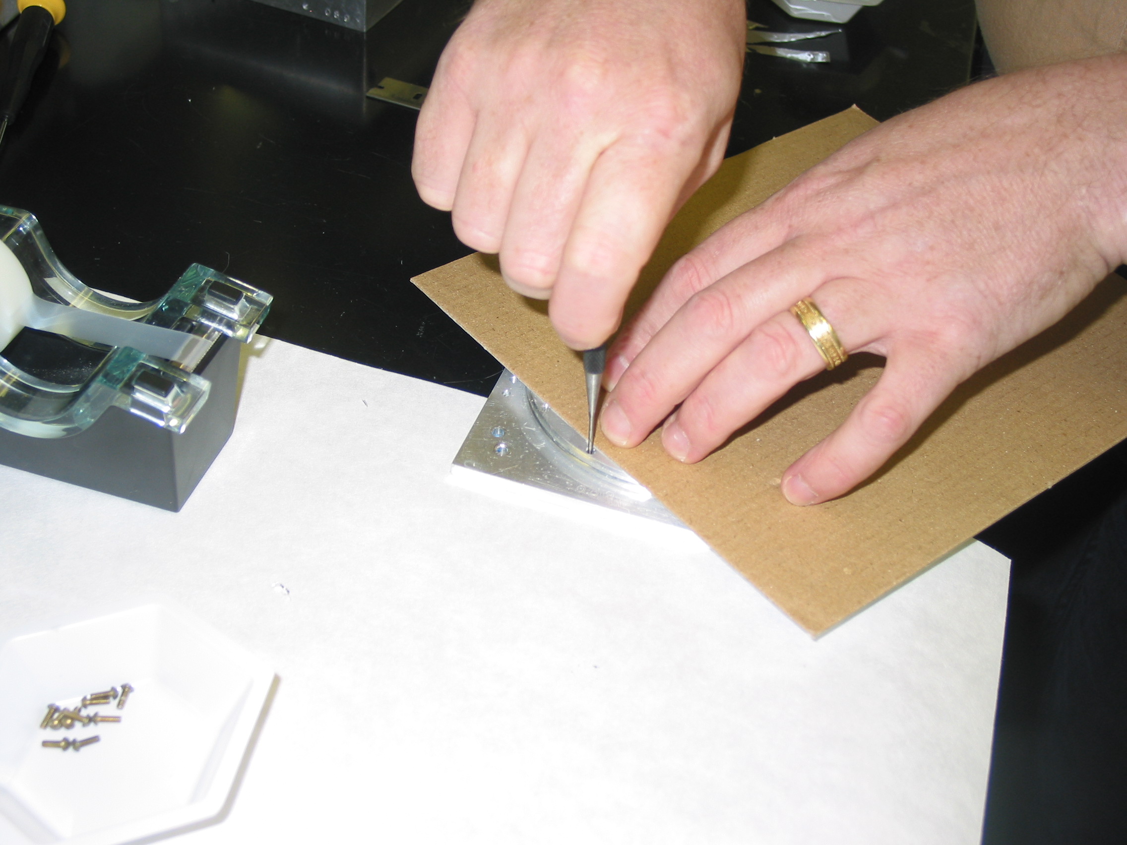
Once the epoxy is dry, take off the weight and cut away to excess mylar to leave a tightly stretched mylar window. The screw holes will have some epoxy in them. To clear them out, place the ring with the mylar over the non-threaded ring, and poke a sharp needle through the hole. Be careful not to puncture the window (sending you back to Step 2!). Holding a piece of cardboard over the window seems to work – and yes, I have poked a hole in the window at this stage!
Once the holes are through, screw the two rings of the front plate together. Again, I use the cardboard to prevent the screwdriver from puncturing the window. Check the conductivity on both sides of the plate. Ideally, the window conducts on both sides. It should definitely conduct on the inside of the chamber (the side of the ring with the screw heads). Using a small amount of silver paint along the inside of the ring can improve the connectivity.
Step 5: Re-assemble the stack of conducting rings
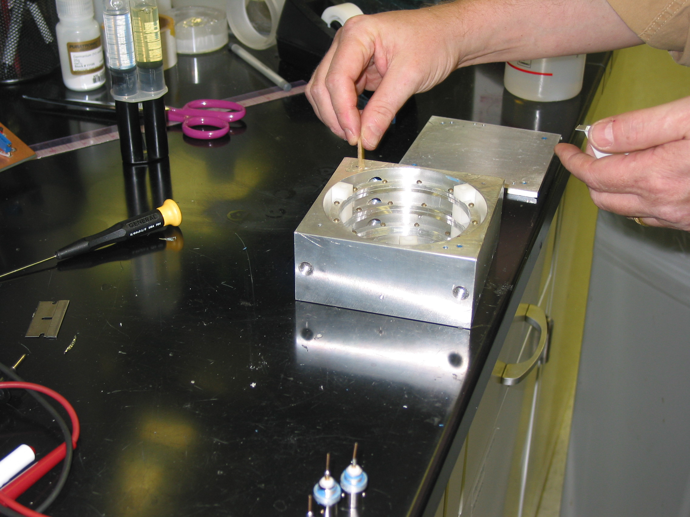
First, using a small amount of epoxy, glue the teflon ring at the bottom of the chamber. This teflon ring insulates the front conducting plate from the box (which is at ground). The epoxy keeps the ring from slipping around and also helps to seal in gases. Next place the front ring in place, and the put the assembly with the middle and back ring on.
Step 6: Re-attache the BNC connectors
Reattach the BNC connectors and test that they each make electrical contact with the corresponding ring. Checking the front and back plate are straightforward. The middle plate can be checked using the holes for the gas inlet/outlet on the side of the chamber opposite the BNC connectors. Based on my own experience, I strongly advise you to check the connections before you epoxy the chamber together!
Step 7. Final assembly
Glue the back plate on, and screw it together using the 4 screws provided, again using Devcon 2-ton epoxy (see Fig 1), not that nasty blue RTV stuff.
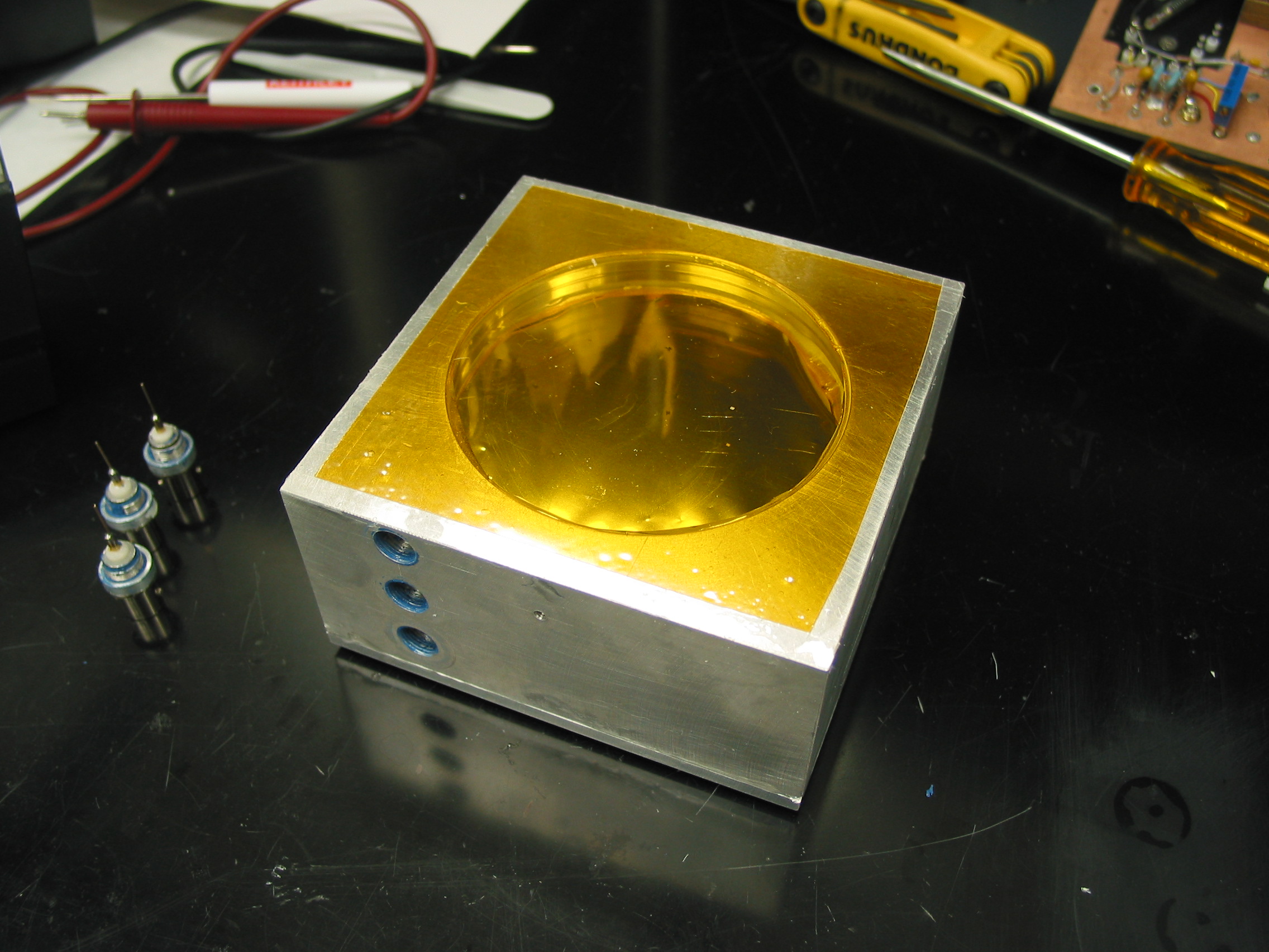
Optionally (but a good idea, especially since you’ve just replaced a broken window, is to glue a piece of thin sheet of kapton to the front of the chamber. This will help protect the mylar window and give a better seal for inert gases.
Finally, if desired, re-attach the electronics box.
